
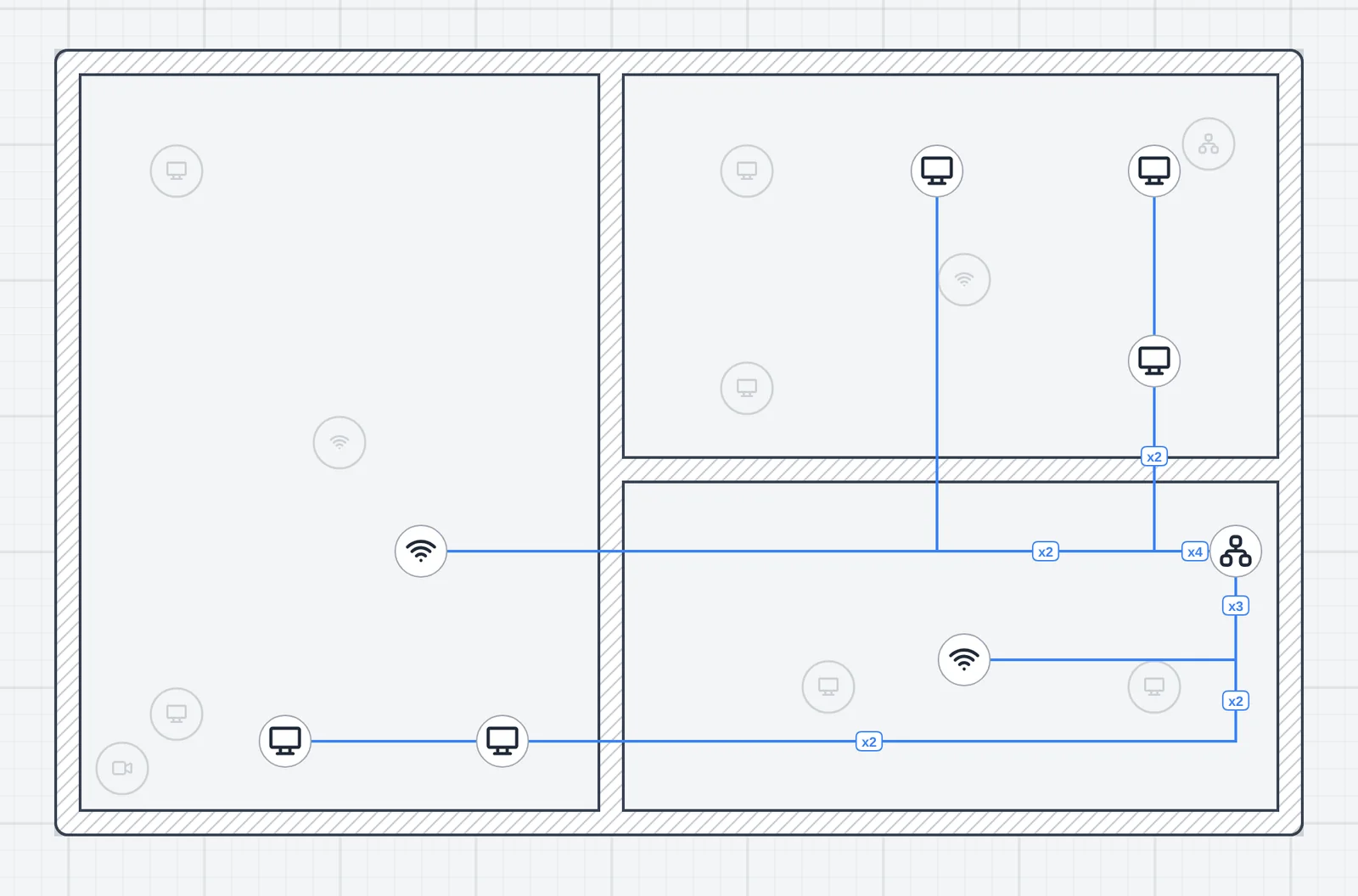
Plenty of the sites we quote have more than one floor: classrooms upstairs, an office over a shop, a clinic on three levels. A Strucit project now holds the whole building: a plan per floor, cables that go from one floor to the next through risers, and a Wi-Fi heatmap that counts the access points above and below.
One project, a plan per floor
- The floor menu in the top bar adds a floor above the one you are on, renames, moves and deletes floors, and switches between them. Alt+↑ and Alt+↓ go up and down a floor.
- Each floor is its own plan, with its own walls, devices, cables, reference image and undo history.
- Start a floor from another one. Copy walls from… brings another floor’s walls up in one step, and Align to lines a floor’s reference image up with the faded floor in two pairs of clicks.
- Stairs offer the next floor. Place stairs on the top floor and Strucit asks “Add a floor above these stairs?”. The new floor starts with a copy of the stairs in the same place.
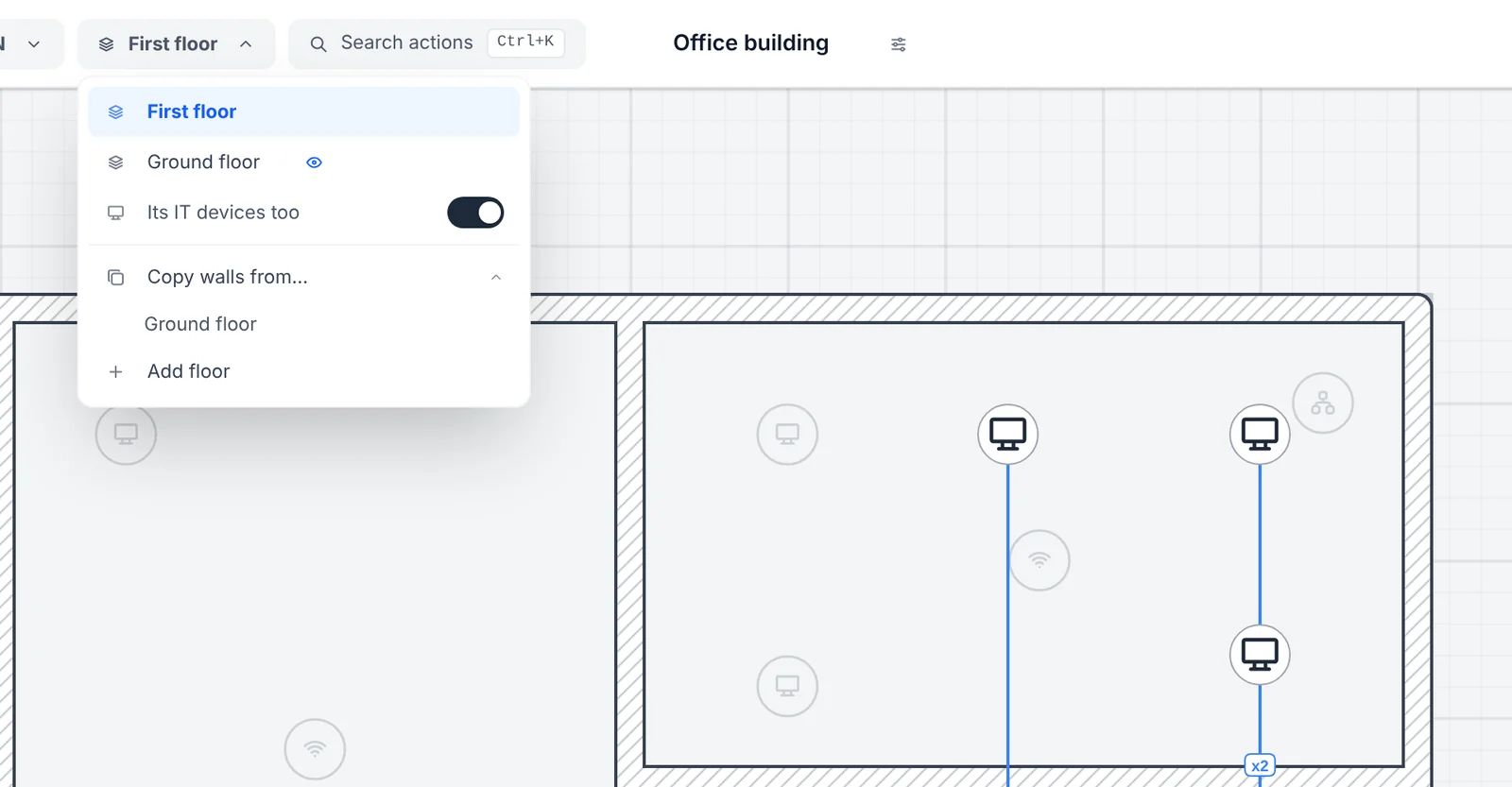
The floor under the one you are on is drawn faded: its walls and stairs, and its IT devices if you turn them on. You place against it: the AP over the corridor below, the riser at the same point on both floors. The eye in the floor menu picks another floor to show, or none.
Wi-Fi through the slab and up the stairwell
The Wi-Fi heatmap counts the access points on the floor right above and right below the one you are looking at. Each of them loses a concrete slab (18.5, 28 and 32.5 dB at 2.4, 5 and 6 GHz) plus the floor-to-floor height as distance, then goes through this floor’s walls like any other AP. Floors two away are left out.
Stairs are a hole in the slab. Stairs placed on a floor go up from it, so the opening between two floors is at the lower floor’s stairs, and an AP on the next floor also reaches yours through it, with no slab loss, only the distance. That is often why the landing upstairs has signal while the rooms around it don’t.
The coverage percentage, the PDF’s Wi-Fi sheets and the automatic AP placement all count these neighbours, so a floor already well lit from below gets fewer suggested APs.
Risers: cables between floors
A riser is the vertical path between floors: a shaft, a vertical tray or conduit, or just a sleeve through the slab. The Riser tool, in the Build group after Tray / conduit, places one at a point. It spans a range of floors, shows on each of them with its floors written under it, and moving it on one floor moves it on all of them. In its menu you set its kind (tray, conduit with a size, or sleeve) and the floors it runs between.
Wiring through it works the way you would draw it by hand:
- On the lower floor, draw the cable from the switch and end it on the riser.
- On the floor above, the riser shows that cable as an open end, ringed in red with “1 from Ground floor”.
- Start a cable on the riser and take it to the switch, AP or PC on that floor.
The connections popup and the rack’s Ports tab then name the device at the other end with its floor. Trays and conduits ending on a riser carry their cables through it.
What a riser adds to the numbers:
- Vertical length. Each cable through a riser gets the height between its two floors. Each floor has its own floor-to-floor height, set in the floor menu: 4 m by default, with quick picks for commercial (4 m) and residential (3 m) buildings.
- Spare cable. Each cable gets 4 m of spare per riser it goes through, for the service loop. It is a setting; 0 turns it off.
- Everywhere it counts. The cable list shows it (“of which … through risers, … of it spare”), and so do the totals, the cables by type, the PDF and the 90 m copper warning. A riser plus two floor runs can pass 90 m when each run alone doesn’t.
- The riser’s own material. A tray or conduit riser counts its own height once, and a conduit riser’s fill counts the cables in it. A sleeve adds no material.
One report and one PDF for the building
- Every floor in the totals. The equipment list, cabling and totals cover the whole building.
- Room and floor beside every device. The text and PDF reports name each device with the room it stands in and its floor, as in “PC 1 (Reception · Ground)”, so the technician knows where to go.
- Numbered through the building.
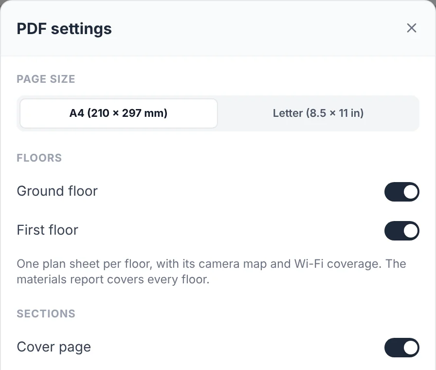
PC #2is the second PC in the building, not the second on some floor. - A sheet set per floor. Pick the floors in the PDF settings; each one gets its plan, camera map and Wi-Fi sheets, titled with the floor.
Free and Pro
A free project has one floor. More floors, and with them risers and Wi-Fi between floors, are Pro, paid by the project owner’s plan: people invited to edit a Pro owner’s project add floors with a free account. The heatmap and the PDF are Pro, as is setting your own floor height and spare cable defaults in your profile. The multiple floors page has the details.
Got a building to quote? Open Strucit, add a floor above your plan and draw your first riser.